
Views: 0 Author: Site Editor Publish Time: 2026-10-08 Origin: Site


Linear motion components define the success of modern machine design. The choice of drive mechanism directly dictates system precision, repeatability, and overall reliability. Engineers face a constant dilemma during the design phase. Over-specifying components inflates bill-of-materials requirements unnecessarily. Under-specifying leads to unacceptable tolerances, rejected parts, or premature mechanical failure. You need a clear framework to make the right choice.
The fundamental manufacturing differences between rolled and ground threads drive performance. Understanding these differences sets up an evidence-based selection process. We will explore how manufacturing methods dictate mechanical capabilities. This guide provides the technical foundation you need when evaluating a rolled vs ground ball screw for your next automation project.
Manufacturing Impact: Ground ball screws are machined for sub-micron precision, while rolled ball screws are cold-formed for high-volume efficiency and structural durability.
Accuracy Classes: Ground screws typically dominate ISO/JIS grades C0–C5; rolled screws generally fall into grades C7–C10, though advanced rolling techniques are increasingly blurring these lines.
Cost Delta: Ground variants can cost significantly more than rolled variants, requiring strict justification based on application tolerances and lifecycle requirements.
Application Fit: Selection must be dictated by a matrix of required lead accuracy, rigidity, critical speed, duty cycle, and budget constraints rather than default preferences.
Manufacturers produce rolled threads using a high-pressure extrusion process. Blank steel rods pass through massive rotating dies typically made of high-speed steel or carbide. These dies physically displace the metal to form the helical thread profile. This cold-forming process does not remove any material. Instead, it reshapes the steel under extreme pressure, forcing the material to flow into the desired geometry.
Cold working provides significant metallurgical benefits. The process creates an uninterrupted grain structure along the thread profile. This continuous grain flow increases surface hardness and boosts overall yield strength. The resulting threads resist wear and handle shock loads exceptionally well. High-volume production lines favor this method for its speed and efficiency, allowing for continuous lengths of threaded rod to be produced rapidly.
Cold forming has distinct limitations regarding absolute precision. Achieving ultra-tight lead tolerances remains difficult because the steel naturally experiences spring-back after passing through the dies. This material memory prevents the microscopic precision seen in machined alternatives. Additionally, the bulk-rolled stock features a hardened outer case. Secondary end-journal machining often requires localized annealing. Machinists must soften the ends using induction heating to cut bearing journals without destroying their cutting tools.

Ground threads begin as case-hardened steel blanks. Manufacturers use specialized abrasive grinding wheels, often embedded with cubic boron nitride (CBN) or aluminum oxide, to cut the helical grooves directly into the hardened material. This subtractive process removes metal slowly and deliberately. The grinding machine passes over the shaft multiple times, utilizing heavy flood coolant to prevent metallurgical burn and maintain dimensional stability.
This method offers unparalleled control over thread geometry. Machinists can dictate pitch, root diameter, and surface finish at a microscopic level. The abrasive cutting action ignores material spring-back. The resulting threads match the theoretical CAD models almost perfectly. This precision directly translates to smooth motion, exact positioning, and consistent torque across the entire travel length.
The abrasive grinding process is highly time-intensive. Manufacturers cannot produce ground shafts at the same speed as rolled shafts. Custom end-machining usually occurs during the primary production cycle rather than as a secondary operation. The machinist turns the bearing journals before the final thread grinding takes place, ensuring perfect concentricity between the support bearings and the ball track.
Recent technological advancements have disrupted the traditional manufacturing divide. Tooling manufacturers now produce extrusion dies with unprecedented accuracy. Modern factories implement strict temperature control during the cold-forming process. These improvements minimize thermal expansion and material spring-back during rolling, resulting in a much more consistent thread profile.
These upgrades allow premium rolled shafts to achieve C5 accuracy grades. Historically, only ground shafts could hit these tolerances. These hybrid options bridge the gap for design engineers. They provide better-than-C7 accuracy without demanding the full investment of a ground shaft. You can now specify high-precision rolled Ball Screws for applications that previously required ground components, freeing up resources for other areas of the machine design.
Lead accuracy determines how closely actual travel matches the commanded position. Ground ball screws generally provide higher accuracy and are suited to CNC machines and precision equipment, while rolled screws are more suitable for general automation and material handling. Thermal expansion can affect either type, so precision systems may require cooling or software compensation to maintain accuracy during continuous operation.
Preload reduces backlash and increases rigidity, but ground screws can normally support higher preload with more consistent torque. Rolled screws are better suited to applications with heavy loads and shock forces, although excessive preload may increase wear and heat. Engineers should select the screw based on the required balance of precision, rigidity, fatigue life, and static load capacity.
Ground ball screws have smoother thread surfaces, which reduces friction, heat, and required drive torque. They also operate more quietly, making them suitable for precision and noise-sensitive equipment. Rolled screws have a rougher surface and may produce more friction and noise, but they remain a cost-effective choice for standard industrial applications.
Ball screw speed depends on shaft diameter, RPM, support design, and shaft straightness. Longer or thinner screws are more likely to vibrate or whip at high speeds, while larger diameters and stronger end supports improve stability. Ground screws generally offer better straightness for high-speed operation, while rolled screws may require lower speeds or additional support to avoid resonance.
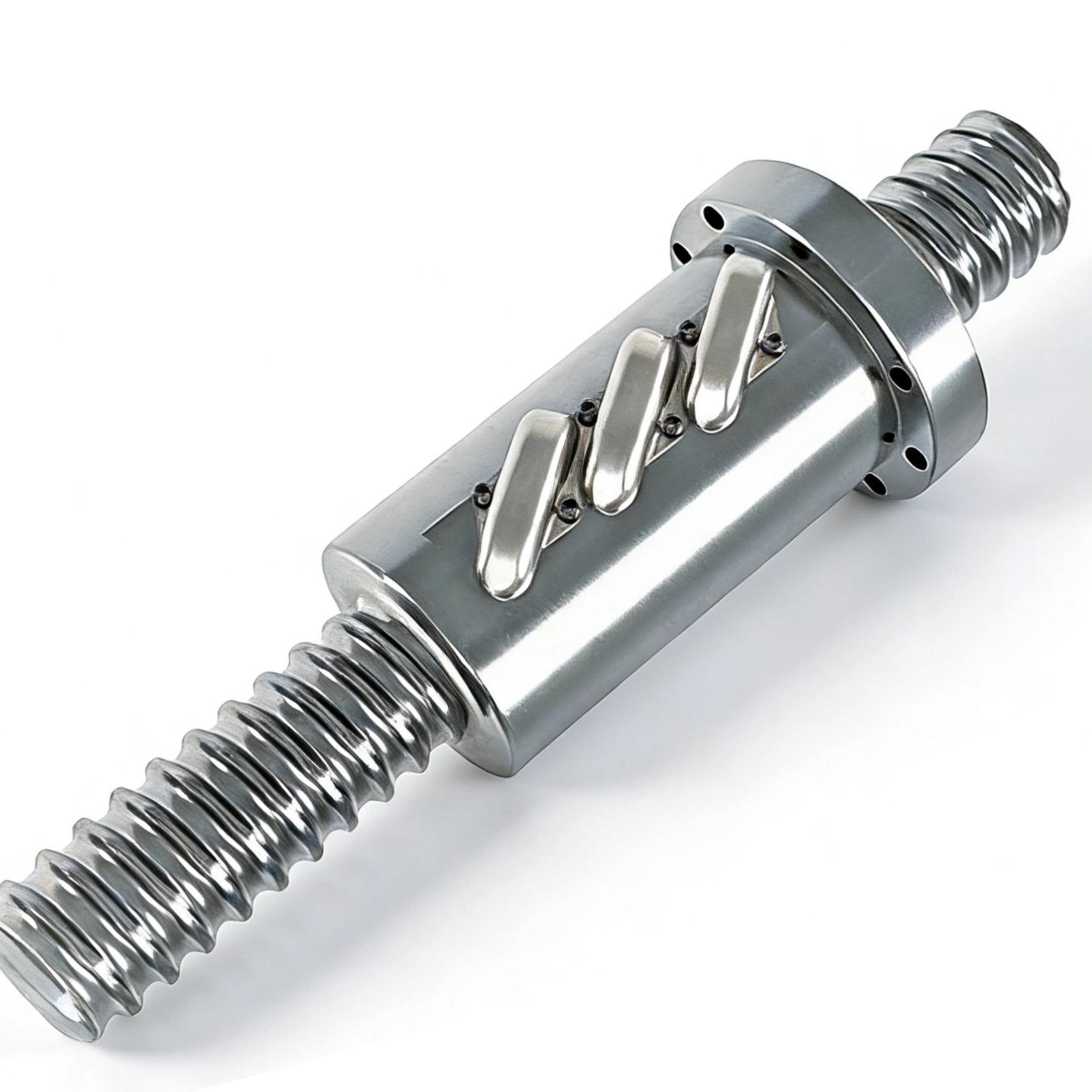
Ground ball screws cost more because they require precision grinding and customized manufacturing. Rolled ball screws are often available as standard stock, making them cheaper and faster to deliver. Ground screws usually require longer lead times, so replacement and project schedules need more advance planning.
Ground ball screws provide excellent accuracy and long service life in high-speed, precision applications when properly lubricated and protected. Rolled screws are more economical for heavy-duty systems exposed to vibration and shock loads. The best choice depends on whether the application prioritizes precision or rugged, cost-effective operation.
| Feature | Rolled Ball Screws | Ground Ball Screws |
|---|---|---|
| Manufacturing Method | Cold-formed extrusion | Abrasive precision grinding |
| Typical Accuracy Grade | C7 - C10 (Precision up to C5) | C0 - C5 |
| Surface Finish (Ra) | 0.4 to 0.8 microns | 0.1 to 0.2 microns |
| Preload Capability | Low to Medium | High to Very High |
| Shock Load Resistance | Excellent (Continuous grain flow) | Good |
| Lead Time Availability | High (COTS availability) | Low (Custom manufactured) |
Rolled ball screws are well suited to automation, packaging, robotics, 3D printers, woodworking equipment, medical beds, and material handling where high repeatability is more important than extreme positioning accuracy. Their lower cost makes them practical for large-scale equipment, and closed-loop systems with linear encoders can further improve positioning accuracy when required.
Ground ball screws are designed for applications requiring very high accuracy, rigidity, and low backlash, such as CNC machine tools, aerospace equipment, semiconductor systems, and precision inspection machines. Their precise thread geometry provides stable motion under demanding loads and helps maintain accurate positioning where software compensation alone cannot correct mechanical backlash or structural movement.
Proper alignment is essential for ball screw life and accuracy. The ball nut should mainly carry axial loads, while linear guide rails handle radial and side forces. End supports such as fixed-supported or fixed-fixed configurations provide different levels of rigidity and speed capability, but all require accurate installation. Keeping the screw parallel to the guide rails helps prevent binding, excess motor load, and premature wear.
| Bearing Support Configuration | Critical Speed Factor | Rigidity Level | Alignment Difficulty |
|---|---|---|---|
| Fixed - Free | 0.36 | Low | Low |
| Supported - Supported | 1.00 | Medium | Medium |
| Fixed - Supported | 1.47 | High | High |
| Fixed - Fixed | 2.23 | Very High | Very High |
Ball nut design should match the machine’s space, accuracy, and speed requirements. Flanged nuts are easy to mount and provide good rigidity, while cylindrical nuts suit compact systems. Double-nut designs allow preload adjustment and are suitable for low-backlash applications. External ball returns are durable and work well for heavy loads, while internal returns are more compact, quieter, and better suited to high-speed precision systems.
Dust, chips, and other contaminants can quickly damage ball tracks and reduce accuracy, especially on precision ground screws. Proper lubrication, protective wipers, and covers such as bellows or telescopic shields are essential for reliable operation. Automatic lubrication can further reduce wear by maintaining a consistent oil or grease film. Before selection, engineers should also confirm lead accuracy, load conditions, speed limits, and support configuration to ensure the ball screw system matches the application.
A: Yes, manufacturers can achieve zero backlash by using oversized balls or preloaded double-nut assemblies. However, due to microscopic inconsistencies in the cold-formed thread profile, applying high preload causes torque variations. This leads to uneven wear and reduced lifespan compared to preloaded ground alternatives.
A: Rolled variants can be produced in extremely long, continuous lengths, often up to 6 or 8 meters, because the extrusion process is continuous. Ground variants are strictly limited by the bed length of the precision grinding machine, typically capping out at much shorter lengths.
A: The ISO/JIS scale uses C-grades to define lead error. Ground variants typically cover the ultra-precise C0 to C5 grades. Standard rolled variants cover C7 to C10 grades. Modern precision rolling techniques now allow high-end rolled variants to achieve C5 accuracy.
A: In terms of static load capacity and shock resistance, yes. The cold-forming process creates an uninterrupted grain structure along the thread profile. This continuous grain flow increases yield strength, allowing rolled threads to survive heavy impact forces better than machined threads.
A: Yes, a closed-loop system using a linear encoder can correct for cumulative lead error by reading the actual carriage position and adjusting the motor output. However, software cannot fix mechanical issues like backlash, vibration, or lack of structural rigidity.

