
Views: 0 Author: Site Editor Publish Time: 2026-10-08 Origin: Site


Incorrect sizing in linear motion systems leads to severe mechanical failures on the factory floor. Engineers frequently face catastrophic buckling, harmonic resonance, or premature fatigue when specifying components improperly. You must balance application requirements against strict physical constraints. Heavy axial loads, rapid traverse speeds, long strokes, and precise lead accuracy demand robust mechanical solutions. However, rotational inertia, spatial limits, and available motor torque restrict your options. Over-engineering the system wastes resources and introduces excessive rotational mass that degrades acceleration. We use a systematic, calculation-based framework for ball screw diameter selection. This approach evaluates load capacity, critical speed limits, stress factors, and end fixity. It ensures optimal system reliability and operational efficiency. By understanding the underlying physics, you can specify components that meet performance criteria without unnecessary bulk or compromised safety margins.
Buckling is the Primary Constraint for Long Strokes: The root diameter must be large enough to withstand peak compressive axial loads without buckling, heavily dictated by the unsupported length and bearing support method.
Speed Limits Dictate Minimum Diameter: Critical speed (the point of resonance or "whipping") and the DN value (Diameter × RPM) establish strict boundaries for rotational velocity based on the chosen diameter.
Inertia Trade-Offs: While a larger ball screw diameter increases load capacity and stiffness, it exponentially increases rotational inertia, requiring larger, more expensive drive motors.
End Fixity is a Force Multiplier: Upgrading bearing supports (e.g., Fixed-Fixed vs. Fixed-Free) can often solve load and speed limitations without requiring a larger, costlier screw diameter.
Preload and Accuracy Interdependence: The chosen diameter directly impacts the system's ability to handle high preloads for zero axial clearance, while desired lead accuracy classes may limit available diameter options.
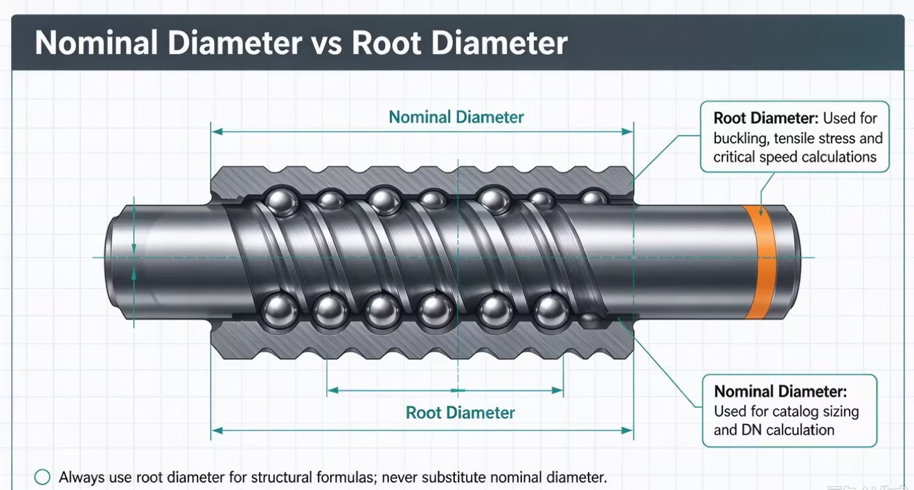
The nominal diameter represents the outer boundary of the ball bearings riding in the thread grooves. Manufacturers use this dimension for general catalog sizing and naming conventions. When you order a 32mm screw, you are referencing this outer boundary.
The root diameter represents the solid steel core of the screw shaft. It is measured at the deepest point of the thread groove. The root diameter serves as the critical metric for all structural calculations. Buckling resistance, tensile strength, and critical speed rely entirely on the cross-sectional area of this solid core. Using the nominal diameter instead of the root diameter in engineering formulas will result in dangerous overestimations of the shaft's structural integrity.
To illustrate the difference, consider standard sizing profiles. The root diameter is always smaller than the nominal diameter, typically by the diameter of the ball bearings used in the nut assembly.
| Nominal Diameter (mm) | Typical Ball Diameter (mm) | Approximate Root Diameter (mm) |
|---|---|---|
| 16 | 3.175 | 12.5 |
| 20 | 3.175 | 16.5 |
| 25 | 4.762 | 19.9 |
| 32 | 6.350 | 25.3 |
| 40 | 7.938 | 31.4 |
| 50 | 9.525 | 39.8 |
Ball screw diameter must be selected alongside lead, length, bearing supports, and motor capacity. Increasing diameter improves rigidity but also raises rotational inertia and torque requirements. Engineers must balance these factors to achieve optimal performance, stability, and efficiency.
A properly selected ball screw diameter ensures adequate load capacity, long service life, minimal vibration, and efficient motor operation. It should support smooth acceleration, maintain positioning accuracy, and fit within the machine's space constraints while minimizing maintenance requirements.

Dynamic load ratings determine ball screw fatigue life, while static load ratings indicate resistance to permanent deformation. Engineers must evaluate both continuous and peak loads to ensure sufficient load capacity, positioning accuracy, and service life.
Long ball screws under compressive loads are vulnerable to buckling. Buckling resistance increases with the fourth power of the root diameter and decreases with unsupported length. Proper diameter selection and safety factors are essential to prevent shaft deformation and structural failure.
Ball screws must withstand tensile and compressive forces without exceeding the material's yield strength. The root diameter determines the shaft's load-bearing cross-sectional area. Selecting an adequate diameter helps prevent permanent deformation and mechanical failure.
Long, horizontally mounted ball screws may sag under their own weight, causing misalignment, increased friction, and reduced positioning accuracy. Increasing the root diameter or adding intermediate supports helps minimize deflection and maintain stable operation.
The method used to support the ends of the screw shaft dramatically alters its load capacity and buckling threshold. Engineers classify end fixity into four primary arrangements. Upgrading the support method acts as a force multiplier, often allowing you to use a smaller diameter shaft.
| Support Method | Description | Buckling Factor | Application Suitability |
|---|---|---|---|
| Fixed-Free | One end rigidly clamped, the other completely unsupported. | 0.25 | Short strokes, vertical loads, low speeds. |
| Supported-Supported | Both ends supported by radial bearings allowing angular deflection. | 1.00 | Moderate lengths, standard industrial applications. |
| Fixed-Supported | One end rigidly clamped, the other supported by a radial bearing. | 2.00 | Long strokes, high speeds, heavy loads. |
| Fixed-Fixed | Both ends rigidly clamped to prevent any angular deflection. | 4.00 | Extreme loads, ultra-high speeds, maximum rigidity. |
By moving from a Supported-Supported arrangement to a Fixed-Fixed arrangement, you quadruple the buckling resistance of the shaft. This structural upgrade saves space and reduces rotational mass by permitting a smaller root diameter. Fixed-Fixed arrangements require precise alignment during installation. Any angular misalignment between the support blocks will induce severe bending stress into the shaft.
Ball screws experience whipping when rotational speed approaches the shaft's natural frequency, causing severe vibration and potential damage. Larger shaft diameters increase critical speed, while longer unsupported lengths reduce it. Operating speed should generally remain below 80% of the calculated critical speed to ensure stability and safety.
The DN value, calculated by multiplying screw diameter (mm) by rotational speed (RPM), indicates a key speed limitation for ball screws. Larger diameters improve resistance to whipping but also increase the DN value. Exceeding the manufacturer's DN limit can damage ball return mechanisms, making it essential to balance shaft diameter and operating speed.
| Return Mechanism Type | Typical DN Limit | Application |
|---|---|---|
| External Tube | 70,000 | Standard automation, low speed |
| Internal Deflector | 100,000 | Machine tools, moderate speed |
| End Cap | 150,000 | High-speed positioning, rapid traverse |
Long-stroke ball screws require sufficient shaft diameter to prevent vibration and buckling, but larger diameters increase rotational inertia and DN limitations. Alternative solutions include rotating nut designs, hollow shafts, and intermediate supports. These approaches improve critical speed, reduce vibration, and maintain stability in high-speed, long-distance applications.
Ball screw diameter and lead directly affect drive torque and mechanical efficiency. Larger diameters may increase friction, while higher lead-to-diameter ratios generally improve efficiency. Proper torque calculations and lubrication are essential to prevent motor overload, overheating, and excessive wear.
Preload eliminates axial backlash and improves positioning accuracy and rigidity. Larger-diameter ball screws can generally support higher preload forces, but excessive preload increases friction and heat. Engineers must select appropriate diameter and preload levels to balance precision, stiffness, and service life.
Ball screw rotational inertia increases with the fourth power of shaft diameter. Doubling the diameter increases inertia by approximately 16 times for the same length and material. Oversized screws require larger motors, increasing energy consumption and system costs. Proper diameter selection balances rigidity, load capacity, and motor efficiency.
| Nominal Diameter | Relative Inertia Multiplier |
|---|---|
| 16mm | 1.0x (Baseline) |
| 20mm | 2.4x |
| 25mm | 5.9x |
| 32mm | 16.0x |
| 40mm | 39.0x |
| 50mm | 95.3x |
As demonstrated, moving from a 16mm to a 50mm shaft increases the rotational inertia by nearly a factor of 100. You must balance the need for structural rigidity against the severe penalty of rotational mass.
Calculate the minimum root diameter required to prevent buckling and tensile yield based on peak loads and unsupported length.
Verify the baseline diameter against critical speed thresholds and manufacturer DN limits to prevent harmonic resonance.
Optimize the end fixity arrangement to maximize structural rigidity and minimize the required shaft size.
Calculate the rotational inertia and drive torque to ensure servo motor compatibility and prevent sluggish acceleration.
Verify the physical dimensions of the selected ball nut against your machine envelope using 3D CAD models.
A: The nominal diameter represents the outer boundary of the ball bearings riding in the thread grooves. Manufacturers use it for general catalog sizing. The root diameter is the solid minor diameter at the bottom of the thread groove. Engineers use the root diameter for all structural calculations, including buckling resistance, tensile stress, and critical speed.
A: Larger diameters increase the cross-sectional area and overall stiffness of the solid steel shaft. This increased rigidity raises the natural frequency of the component. A higher natural frequency allows the system to achieve higher rotational speeds before harmonic resonance, or whipping, occurs during rapid traverse movements.
A: No. While a larger diameter prevents shaft whipping, it eventually hits the DN value limit. The DN value dictates the maximum safe velocity for the ball bearings circulating inside the nut. Exceeding this limit causes the internal return mechanism to fail, destroying the assembly.
A: Upgrading support bearings significantly alters load capacity. Moving from a Fixed-Supported to a Fixed-Fixed bearing arrangement quadruples the buckling resistance and raises the critical speed limit. This structural upgrade often allows engineers to use a smaller, more efficient screw diameter while maintaining safety margins.
A: Engineers use the Euler column formula to calculate buckling load. The maximum compressive force is directly proportional to the fourth power of the root diameter and inversely proportional to the square of the unsupported length. End fixity factors also modify this calculation based on bearing rigidity.
A: Larger diameters generally accommodate larger ball bearings and provide a greater contact area along the raceways. This increases the basic dynamic load rating. A higher dynamic load rating distributes operational forces more effectively, extending the L10 fatigue life of the system under continuous operation.

