
Views: 0 Author: Site Editor Publish Time: 2026-10-08 Origin: Site


Operating a linear motion system near its natural frequency causes shaft whipping, violent vibration, and mechanical failure. Engineers face a tough balancing act on the floor. You have to juggle travel length, shaft diameter, and rotational speed requirements. The goal is hitting aggressive performance targets without over-engineering the machine or wasting budget on oversized components. Validating a linear motion design always starts with the math. Accurate ball screw critical speed calculation factors in your specific end-support configurations, load stresses, and safety margins. It tells you exactly what hardware will survive the application and what will tear itself apart. We will look at the core formulas, evaluate how different mounting setups change your rotational limits, and cover practical field strategies to bypass speed constraints in high-performance automation.
Critical speed is primarily dictated by the root diameter of the screw, the unsupported length, and the rigidity of the end-support configuration.
Industry standards mandate a safety factor, requiring maximum operating speeds to remain at or below 80% of the theoretical critical speed.
Upgrading the end-support configuration (e.g., moving from Supported-Supported to Fixed-Fixed) is often a more cost-effective way to increase speed limits than increasing the screw diameter.
Critical speed calculations must always be paired with DmN (ball velocity) calculations to ensure the internal ball return mechanism can handle the RPM.
Operating too close to the critical speed threshold exponentially degrades the L10 service life of the ball screw due to cyclical stress and dynamic load amplification.
Every rotating shaft has a natural frequency based on its mass, length, and material stiffness. Critical speed is the exact RPM where this frequency gets excited. Hit this speed, and the shaft enters resonance. On the shop floor, we call this shaft whipping. The shaft bows out from its center axis. This creates an eccentric mass that throws violent centrifugal forces into the machine frame. You have to understand this physical limit to design safe, reliable linear motion systems.
If you ignore critical speed limits, you will destroy the machine. When shaft whipping starts, the vibration transfers directly into the support bearings and the nut assembly. This eccentric movement wrecks the concentric alignment you need for precise linear motion. Premature bearing wear happens fast. The steel balls get forced against the raceways with uneven, violent pressure. The system loses positioning accuracy almost immediately. In machining and tooling applications, this vibration transfers straight to the cutting tool. You end up with a terrible surface finish on the workpiece. If you let the machine keep running at resonance, the shaft will eventually snap, or the bearing mounts will rupture completely.
Getting too close to the critical speed threshold introduces unpredictable dynamic loads into the system. These loads drastically cut down the calculated L10 service life of the assembly. The standard L10 life equation assumes smooth, predictable axial loading. Vibration amplifies the fatigue stress on the nut and the internal ball bearings. The relationship between load and bearing life is cubic. That means even a small increase in dynamic stress from vibration will exponentially degrade the lifespan of your components. You have to account for these hidden stresses when evaluating how long the system will actually last in the field.
A successful specification hits the target linear velocity required by the application while keeping a strict safety buffer. The industry standard requires a minimum 20% buffer below the calculated critical speed threshold. This buffer covers real-world operational variables. It accounts for minor alignment discrepancies and manufacturing tolerances that mathematical models cannot predict. Designing within this safe operating zone gives you predictable performance and maximizes component lifespan.
Finding the safe operating limits of a linear motion system requires specific mathematical models. The standard formula gives you a baseline to check shaft stiffness against RPM. Engineers rely on this equation to validate preliminary designs before spending hours on detailed CAD modeling or ordering expensive components.
The standard imperial formula for calculating theoretical critical speed is N = Cs × 4.76 × 10^6 × (d / L^2). For metric calculations, the constant changes based on the specific units used by the manufacturer, but the proportional relationship between the variables stays exactly the same.
N (Maximum Critical Speed): The theoretical rotational speed in RPM where the shaft will experience resonance.
d (Root Diameter): The minor diameter of the shaft. You measure this at the very bottom of the thread groove. Never use the nominal outer diameter for this calculation. The root diameter represents the actual solid cross-section that provides structural stiffness.
L (Unsupported Length): The maximum distance between the support bearings. In systems where the nut travels, this is the total distance between the end supports.
Cs (End-Support Configuration Factor): A mathematical constant representing the rigidity provided by your chosen mounting method.
The theoretical result from the core equation represents the absolute failure point under perfect, laboratory conditions. Real-world applications are never perfect. You must multiply the final theoretical result by 0.8. This is the 80% safety rule. Operating at 80% of the theoretical limit accounts for minute variations in shaft straightness, slight frame deflections, and the natural wear of support bearings over time. If you skip this safety margin, the system will eventually fail.
The standard simplified formula works great for uniform shafts with standard mounting configurations. But highly complex or multi-mass systems need more rigorous analysis. If your design features a stepped shaft with varying diameters, or if you have heavy external masses attached directly to the rotating assembly, you have to use advanced analytical methods. The Rayleigh-Ritz equation and Dunkerley's method let you analyze natural frequencies across non-uniform geometries. These methods determine critical speeds much more accurately than the standard formula, preventing dangerous miscalculations in custom machinery.

How you mount the ends of the shaft directly impacts its overall stiffness and its resistance to whipping. Different mounting configurations provide different levels of rigidity. We represent this mathematically with the end-support factor (Cs). Picking the right configuration is a major engineering decision. You have to balance speed requirements, thermal expansion risks, and overall system cost.
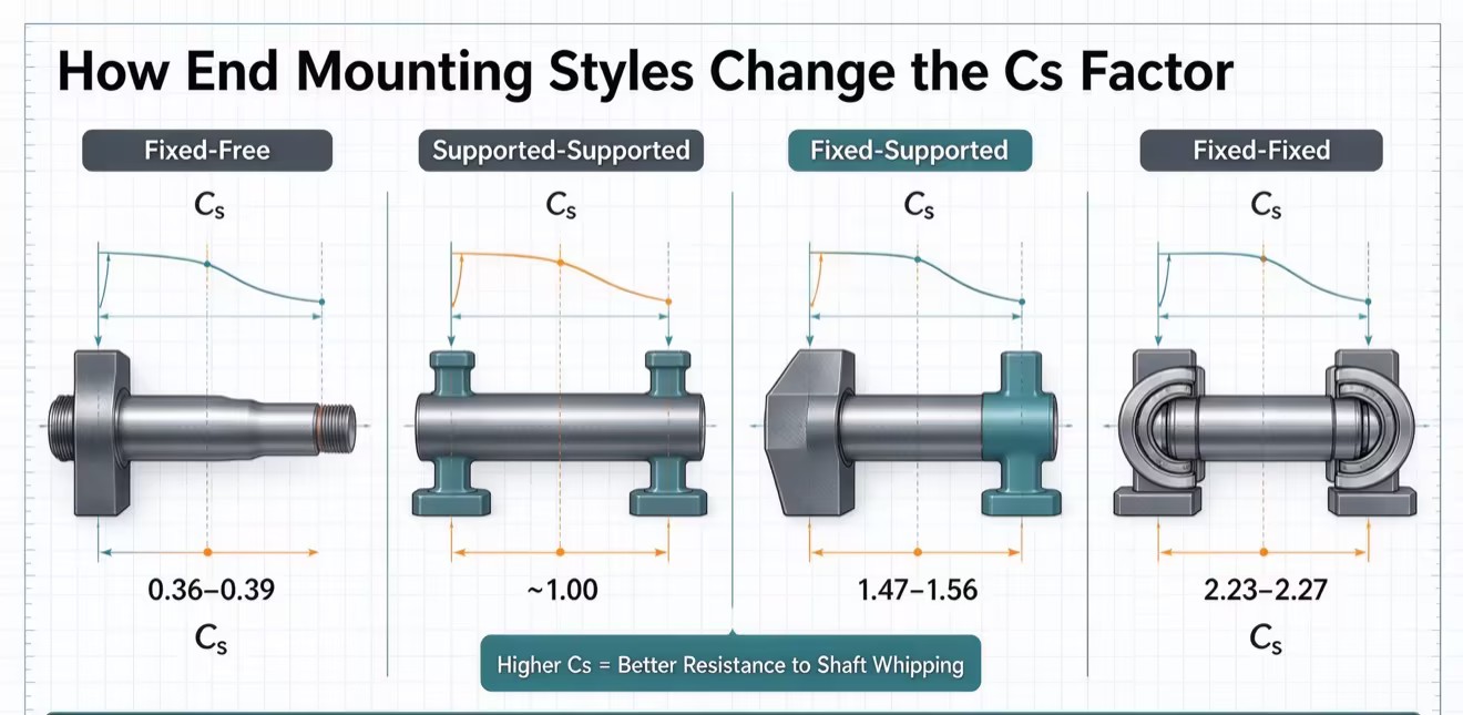
The Fixed-Free configuration secures one end of the shaft in a rigid bearing block and leaves the opposite end completely unsupported. This setup uses the lowest Cs value, usually between 0.36 and 0.39. Because one end floats freely, the shaft has a massive risk of whipping even at low RPMs. You can only use this configuration for very short strokes and low-speed applications. It offers the lowest cost and easiest installation, but it heavily restricts performance. Do not use this for precision automation.
The Supported-Supported configuration uses standard radial bearings at both ends. These bearings support the shaft radially but allow for slight angular deflection. This setup provides a moderate Cs value, usually around 1.0. It is the standard baseline for general linear motion applications. It is cost-effective and relatively easy to align on the shop floor. However, it will bow over long lengths and cannot handle the extreme RPMs required by high-speed machining centers.
The Fixed-Supported configuration secures one end with an angular contact bearing pair. This restricts all axial and radial movement. The other end uses a simple radial bearing. This provides a high Cs value, usually ranging from 1.47 to 1.56. This is the go-to choice for high-precision CNC equipment and advanced automation. It offers great structural rigidity while allowing the supported end to float slightly in the axial direction. You need this floating action to handle the thermal expansion of the shaft as it heats up during continuous operation.
The Fixed-Fixed configuration locks both ends of the shaft using rigid angular contact bearing pairs. This setup gives you the highest possible Cs value, usually ranging from 2.23 to 2.27. It maximizes the RPM potential for long-stroke applications, letting you hit aggressive linear velocities. But implementation carries heavy risks. You need strict alignment tolerances during assembly. Because both ends are locked, thermal expansion will induce severe axial compression forces. You have to manage the heat. This often means using hollow shafts with internal liquid cooling to prevent thermal buckling.
| Configuration Type | Typical Cs Value | Rigidity Level | Primary Application | Thermal Expansion Handling |
|---|---|---|---|---|
| Fixed-Free | 0.36 - 0.39 | Low | Short stroke, low speed positioning | Excellent (Free end expands naturally) |
| Supported-Supported | ~1.00 | Moderate | General automation, packaging | Good (Bearings allow slight float) |
| Fixed-Supported | 1.47 - 1.56 | High | CNC machining, precise robotics | Very Good (Supported end accommodates growth) |
| Fixed-Fixed | 2.23 - 2.27 | Maximum | High-speed, long-stroke aerospace routing | Poor (Requires active cooling or pre-tensioning) |
Engineers often confuse critical speed with the DmN value. Both metrics dictate the maximum allowable rotational velocity of the system, but they measure two entirely different physical limitations. You have to evaluate both metrics independently to ensure the safe operation of a Ball Screw assembly.
Critical speed dictates the physical limit of the long steel shaft. It measures when the shaft itself will start to bend and whip from resonance. The DmN value dictates the internal mechanical limit of the nut assembly. It measures the maximum velocity at which the steel balls can safely travel through the internal return circuits. If you exceed the critical speed, you destroy the shaft. If you exceed the DmN value, you destroy the internal ball return tubes or deflectors. The balls will jam and shatter inside the nut.
The formula for calculating DmN is simple: DmN = Pitch Circle Diameter × Maximum RPM. The Pitch Circle Diameter is the theoretical circle drawn through the center of the balls as they sit in the raceway. Manufacturers usually calculate this as the nominal screw diameter plus a specific constant value based on their proprietary thread geometry. You have to pull the exact Pitch Circle Diameter from the manufacturer's specification sheet to get an accurate DmN calculation.
When you finalize a design, you will have two distinct maximum RPM limits. One comes from the 80% critical speed calculation. The other comes from the DmN limit. The maximum allowable speed of the entire system is always the lower of the two values. If the shaft can handle 3,000 RPM before whipping, but the nut's internal return mechanism fails at 2,500 RPM, your absolute system limit is strictly 2,500 RPM. There are no exceptions to this rule.
During the preliminary design phase, you will often find that your initial component selection fails the critical speed calculation. This happens all the time in high-speed applications requiring 1,500 RPM to 7,500+ RPM over long strokes. When the math fails, you have to apply specific engineering trade-offs to bypass the physical limitations.
Increasing the diameter directly and significantly increases the structural stiffness of the shaft. Because diameter is a numerator in the critical speed equation, a larger shaft inherently resists whipping at higher speeds.
A larger diameter drastically increases the rotational inertia of the system. You will need larger, more expensive servo motors to hit your required acceleration rates. It also increases the overall physical footprint and component weight of the assembly.
The lead defines the linear distance traveled per one full revolution. Selecting a higher lead lets the system hit the exact same linear velocity at a significantly lower RPM. This effectively bypasses the critical speed limit without changing the shaft diameter or length.
A higher lead reduces the mechanical advantage of the system. The motor has to supply higher torque to move the same payload. It alters the dynamic load ratings and will negatively impact the fine positioning resolution of the machine.
Changing the mounting style directly increases the Cs multiplier in the formula. Upgrading from Supported-Supported to Fixed-Supported raises the maximum allowable RPM without requiring any changes to the core shaft geometry or the motor sizing.
Upgrading supports increases mounting complexity. You need stiffer bearing blocks and tighter machining tolerances on the machine frame to ensure perfect alignment.
For extreme lengths where standard solutions fail, we use driven nut systems. In this architecture, the long shaft stays completely stationary. A motor and belt drive system rotates the nut assembly around the fixed shaft to achieve linear motion. Because the shaft never rotates, shaft critical speed is completely eliminated from the equation. This lets you run exceptionally high linear velocities over massive strokes without worrying about shaft whipping.
Define your required linear speed, payload, and total stroke length before selecting any hardware.
Calculate the critical speed using a Supported-Supported baseline to gauge initial design viability.
Consult manufacturer load and speed charts to verify theoretical calculations against proprietary DmN limits.
Adjust support configurations or increase the screw lead to satisfy the 80% safety rule.
A: The industry standard safety factor requires operating at or below 80% of the calculated theoretical critical speed. Engineers apply a 0.8 multiplier to the final equation result. This safety margin accounts for real-world variables like minor alignment deviations, machine frame deflection, and standard manufacturing tolerances that mathematical models cannot perfectly predict.
A: Screw length has an inverse square relationship with critical speed. Because the unsupported length is squared in the denominator of the formula, increasing the length drastically reduces the safe operating speed. If you double the unsupported length of a shaft, its critical speed drops by a factor of four.
A: Critical speed defines the physical resonance limit of the rotating steel shaft, determining when it will begin to whip and bend. DmN defines the internal mechanical speed limit of the nut assembly, determining how fast the steel balls can safely travel through the return circuits without jamming or shattering.
A: Yes. Applying axial tension to a shaft in a Fixed-Fixed mounting configuration increases its overall structural stiffness. This added rigidity raises the natural frequency of the shaft, which subsequently increases the critical speed threshold, allowing for higher RPMs in long-stroke applications.
A: The root diameter is the measurement taken at the very bottom of the thread groove. It cannot be accurately estimated from the nominal outer diameter. You must source the exact root diameter directly from the manufacturer's technical specification sheets for the specific part number you are evaluating.
A: Operating near the critical speed induces severe vibration and resonance. This creates unpredictable, amplified dynamic loads on the nut and bearings. Because bearing life calculations rely on a cubic relationship with load, these cyclical stresses exponentially reduce the L10 service life of the entire assembly.

