
Views: 0 Author: Site Editor Publish Time: 2026-10-08 Origin: Site


Specifying linear motion components represents a strict engineering bottleneck. Minor miscalculations here lead to catastrophic mechanical failures, excessive downtime, or bloated system requirements. Selecting the wrong lead forces you to compromise the entire machine design. You either oversize servo motors to compensate for lost mechanical advantage, sacrifice cycle times due to strict RPM limits, or fail to meet tight positioning tolerances on the shop floor. We need a systematic, evidence-based framework for evaluating these components against the competing demands of linear velocity, axial thrust, and micron-level accuracy. This ensures optimal ball screw lead selection. Getting this right dictates whether a machine runs flawlessly for a decade or tears itself apart during initial commissioning. We will break down the exact math, mechanical limits, and real-world trade-offs required to size your linear drivetrain correctly the first time.
The Engineering Triangle: Increasing ball screw lead yields higher linear speeds at lower RPMs but proportionally reduces mechanical advantage, requiring higher motor torque to achieve the same thrust.
Resolution Constraints: Finer positioning resolution requires a smaller lead, which inherently limits maximum linear velocity due to the critical speed (whipping) limits of the screw shaft.
System-Level Sizing: Proper ball screw lead selection cannot occur in a vacuum; it must be calculated concurrently with motor torque curves, encoder resolution, and dynamic load ratings (L10 life).
Risk Mitigation: Over-specifying lead to achieve faster cycle times often introduces back-driving risks and necessitates larger, more expensive braking systems.
Engineers frequently use the terms "lead" and "pitch" interchangeably, but they represent entirely different geometric measurements. Lead refers to the exact linear distance the ball nut travels during one complete 360-degree rotation of the screw shaft. Pitch measures the linear distance between adjacent threads on the screw. These two values only equal each other on a single-start screw. If you specify a multi-start screw, the lead equals the pitch multiplied by the number of starts. For example, a screw with a 5mm pitch and two starts has a 10mm lead. Understanding this distinction prevents massive positioning errors during the initial design phase and ensures the controller scales the motor pulses correctly.
Validating the choice of a ball screw over a traditional acme lead screw establishes our mechanical baseline. Ball screws utilize recirculating steel balls to reduce friction, achieving mechanical efficiencies exceeding 90%. This makes them ideal for high-speed and high-load applications where heat generation must remain low. However, this high efficiency eliminates the inherent self-locking benefit found in fine-lead acme screws, which operate on sliding friction at around 30% to 40% efficiency. Without self-locking friction, selecting the correct Ball Screw Lead becomes a primary factor for load holding and preventing unwanted back-driving when motor power is removed.
Think of the lead as the mechanical transmission ratio between your rotary motor and your linear payload. Just like a gearbox in a vehicle, the lead dictates how rotary power converts into linear work. A smaller lead acts like a low gear, providing massive thrust at the expense of top speed. A larger lead acts like an overdrive gear, delivering high linear velocity but requiring substantial torque to accelerate the payload. You must balance this ratio to match your specific application requirements, ensuring the motor operates within its continuous torque range.
Grounding theoretical calculations in procurement reality saves engineering time and project budget. Manufacturers produce ball screws in standard metric leads to streamline production. Designing your system around standard available leads ensures easier sourcing, simpler replacement, and predictable performance data.
5mm Lead: The industry standard for high-thrust, high-precision applications like CNC milling machine axes.
10mm Lead: The versatile middle ground, offering a balance of moderate speed and acceptable mechanical advantage for general automation.
16mm to 20mm Lead: Geared toward high-speed packaging equipment, laser cutting gantries, and rapid pick-and-place systems.
25mm+ Lead: Extreme speed applications where cycle time is the absolute priority and payload mass is relatively low.
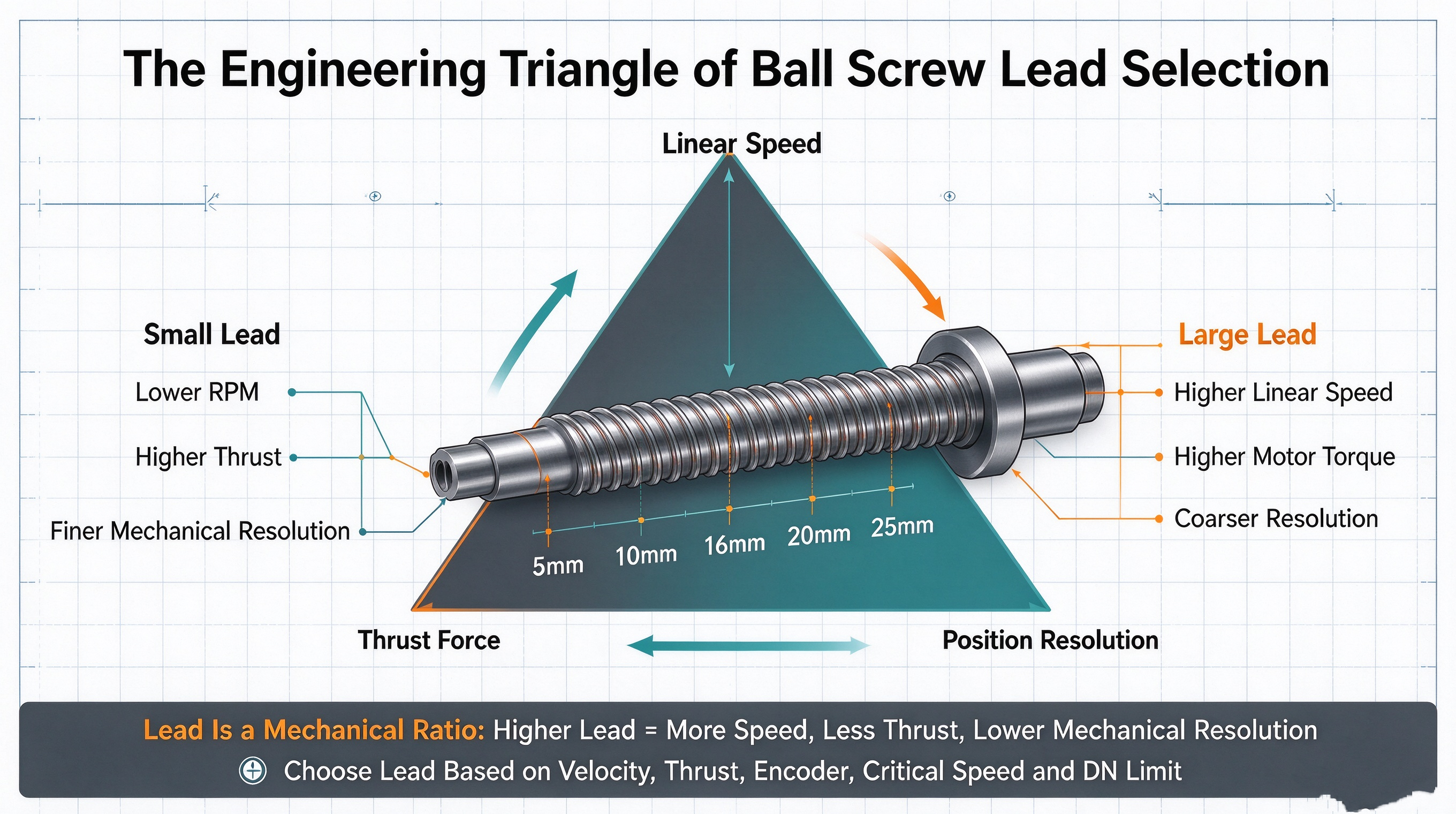
An unavoidable inverse relationship exists between linear speed and positioning resolution. A high lead, such as 25mm, covers significant ground per revolution. This achieves rapid cycle times but makes sub-micron positioning difficult. To achieve tight tolerances with a high lead, you depend entirely on ultra-high-resolution encoders and extremely stiff control loops. Conversely, a 5mm lead naturally provides finer mechanical resolution. Each degree of motor rotation translates to less linear movement, making it easier for the controller to hit precise target positions without hunting or oscillating around the setpoint.
Mechanical advantage dictates your motor sizing. A lower lead acts as a mechanical gear reduction. It multiplies the motor torque, converting it into high axial thrust. This allows you to move heavy loads using a relatively small, compact servo motor. When you select a high lead for speed, you lose this mechanical advantage. Moving the exact same mass with a 20mm lead demands significantly more continuous motor torque than moving it with a 5mm lead. This directly impacts your drive sizing, electrical cabinet space, and power requirements.
The extreme efficiency of ball screws introduces back-driving risks. Higher leads significantly lower the friction threshold required for the payload to back-drive the motor. In vertical applications, gravity acts continuously on the payload. If the lead is too high, the mass will force the screw to rotate backward the moment power drops or the servo drive faults. This necessitates the integration of holding brakes or pneumatic counterbalances, adding mechanical complexity, wiring, and weight to the Z-axis assembly.
Mapping common lead choices to real-world applications provides a practical starting point for your design. For high-thrust, high-precision environments like metal cutting, engineers typically select 4mm to 5mm leads. These provide the necessary cutting force and rigid positioning to resist tool deflection. For high-speed packaging equipment where cycle time dictates throughput, engineers favor 20mm to 25mm leads. These profiles help you align your initial calculations with proven industry standards before diving into the complex math.
Determining your motor requirements starts with a foundational formula: RPM = (Linear Velocity × 60) / Lead. Lead selection directly controls motor velocity. If your application requires a linear velocity of 1000 mm/sec, a 5mm lead demands a staggering 12,000 RPM from the motor. This exceeds the capabilities of standard industrial servos. By doubling the lead to 10mm, you halve the required motor speed to 6,000 RPM. Increasing the lead to 20mm drops the requirement to a highly manageable 3,000 RPM.
| Target Linear Velocity | Screw Lead | Required Motor RPM | Feasibility with Standard Servos |
|---|---|---|---|
| 1000 mm/sec | 5 mm | 12,000 RPM | Impossible (Requires custom spindle motor) |
| 1000 mm/sec | 10 mm | 6,000 RPM | Borderline (Requires high-speed servo) |
| 1000 mm/sec | 20 mm | 3,000 RPM | Standard (Easily achievable) |
| 1000 mm/sec | 25 mm | 2,400 RPM | Standard (Optimal for continuous duty) |
Critical speed represents the rotational frequency that excites the natural frequency of the screw shaft. Hitting this speed causes destructive vibration known as whipping. Whipping destroys support bearings, damages the ball nut, and ruins positioning accuracy. Longer screw shafts have lower critical speeds. A larger lead helps you achieve your target linear speed while keeping the motor RPM safely below this critical threshold. End-fixity heavily influences this limit. A shaft supported by fixed bearings at both ends can spin much faster than a shaft fixed at one end and floating at the other.
The DN value acts as the limiting factor for the steel balls circulating inside the nut. You calculate it by multiplying the nominal diameter of the screw (in millimeters) by the maximum RPM. Manufacturers set strict maximum DN ratings to prevent the recirculating balls from shattering or jamming the return tubes due to excessive centrifugal force. Standard return tubes might handle a DN of 70,000, while high-speed end-cap deflectors can handle up to 100,000. Your lead selection must ensure that the required RPM to hit your target velocity does not push the assembly past its rated DN limit.
To determine the motor torque required to move your load, use the standard conversion formula: Torque (Nm) = (Thrust (N) × Lead (m)) / (2π × Efficiency). This equation proves that lead serves as the primary variable dictating motor sizing. If you require 5000N of thrust and use a 10mm (0.01m) lead with 90% efficiency, you need approximately 8.8 Nm of continuous torque. If you double the lead to 20mm to gain speed, you must double the motor torque to 17.6 Nm to maintain the same axial thrust. You cannot change the lead without recalculating your entire torque profile.
Selecting a high-lead screw strictly for speed introduces harsh spatial realities on the machine frame. Requiring more torque means specifying a larger servo or stepper motor. Larger motors require larger drives, thicker gauge cables, and higher-capacity power supplies. This increases the physical footprint of your electrical cabinet and adds significant weight to moving gantries. You must weigh the benefit of faster cycle times against the physical constraints of integrating larger electromechanical components into your machine architecture.
Lead geometry impacts the internal construction of the ball nut. A higher lead often means fewer load-bearing balls engage the thread circuit at any given time compared to a fine-lead nut of the exact same length. This reduction in contact points lowers the dynamic load rating (Ca). When calculating the L10 life expectancy—the theoretical life 90% of identical screws will reach before fatigue flaking occurs—you must account for this.
Determine the equivalent axial load (Fm) based on your motion profile.
Identify the Dynamic Load Rating (Ca) from the manufacturer's catalog for your specific lead.
Calculate life in revolutions: L10 = (Ca / Fm)³ × 10⁶.
Convert revolutions to hours based on your average RPM. A higher lead lowers your average RPM for a given speed, which can sometimes offset a lower Ca value and extend the life in hours.
Mechanical lead and electronic encoders work together to define your system's resolution. Calculate linear resolution per encoder count using this formula: Linear Resolution = Lead / Encoder PPR (Pulses Per Revolution). A 10mm lead paired with a 10,000 PPR encoder yields a theoretical resolution of 0.001mm per pulse. If you increase the lead to 20mm, your resolution drops to 0.002mm per pulse. To maintain the original resolution with a faster lead, you must upgrade to a higher-resolution encoder and ensure your controller's processor can handle the increased pulse frequency.
Manufacturers grade ball screws based on lead accuracy, typically using classes like C3, C5, or C7. Your chosen lead interacts with these accuracy grades. Additionally, backlash—the axial play between the nut and the screw—destroys repeatability upon direction reversal. If your application demands high precision, you must specify preloaded nuts to eliminate backlash, regardless of the lead you select.
| Accuracy Grade | Allowable Travel Variation (per 300mm) | Typical Application |
|---|---|---|
| C3 | 0.008 mm | Aerospace, Precision CNC, Semiconductor |
| C5 | 0.018 mm | Standard CNC, High-precision automation |
| C7 | 0.050 mm | General automation, Packaging, Transport |
Friction generates heat, and heat causes steel to expand. Temperature fluctuations alter the effective lead over long strokes. A standard steel screw expands roughly 12 microns per meter per degree Celsius. Higher leads operating at high velocities generate more friction, compounding thermal growth. If a 1-meter screw heats up by 10 degrees Celsius during operation, it grows by 120 microns. If you do not map this thermal expansion and compensate for it within the motion controller, your positioning errors will stack up over the length of the travel, ruining part tolerances.
Begin by mapping out the hard limits of your application. You must quantify the total stroke length, maximum payload mass, required cycle time, and strict positioning repeatability. These non-negotiable constraints form the boundaries of your selection process. Without exact numbers for mass and target velocity, any lead selection remains a guess. Document these figures clearly before looking at manufacturer catalogs or sizing software.
Determine the minimum acceptable lead that keeps your motor RPM safe. Use your target linear velocity to calculate required RPMs across various standard leads. Cross-reference these RPMs against the screw's critical speed limit (based on stroke length and end-fixity) and the nut's maximum DN rating. Eliminate any lead that forces the system to operate above 80% of these critical mechanical thresholds to leave a safety margin.
Take the minimum safe lead identified in Step 2 and cross-reference it against your motor's encoder resolution. Ensure the target positioning accuracy remains mathematically possible. If the required lead degrades your mechanical resolution too far, you must either upgrade your encoder, tighten your control loop tuning, or accept a slower cycle time to utilize a finer lead.
Calculate the continuous and peak torque required for your shortlisted lead. Factor in the mass of the payload, acceleration rates, and friction coefficients of the linear guides. If the resulting torque requires a motor that is too large or too heavy for your machine's footprint, you must iterate. Adjust the lead, consider a different screw diameter, or add a gearbox to multiply torque, keeping in mind a gearbox will reduce your top speed.
Consider moving a 50kg payload over a 1000mm stroke at 1 meter per second. A 5mm lead requires 12,000 RPM. A 1000mm shaft spinning at 12,000 RPM will violently whip and fail. We must increase the lead. A 20mm lead drops the requirement to 3,000 RPM, well below the critical speed of a standard 20mm diameter shaft with fixed-supported ends. Next, we calculate torque. The 20mm lead requires four times the acceleration torque of the 5mm lead. We size the servo motor to handle this specific torque profile, successfully balancing speed limits against mechanical advantage.
Input your payload, stroke, and velocity data into manufacturer sizing software to establish a baseline critical speed limit before finalizing any mechanical drawings.
Calculate the exact thermal growth expected for your stroke length and program the necessary compensation offsets into your motion controller.
Specify a holding brake on the servo motor for any vertical axis utilizing a lead greater than 5mm to prevent catastrophic back-driving during power loss.
Verify the DN value of your selected nut against the maximum RPM required for your fastest rapid traverse move to prevent bearing failure.
A: Lead is the linear distance the nut travels in one full 360-degree rotation of the screw. Pitch is the linear distance between adjacent threads. They are only equal on single-start screws. On multi-start screws, lead equals pitch multiplied by the number of starts.
A: Ball screws use recirculating bearings, offering over 90% efficiency, making them ideal for high speeds and heavy loads without excessive heat. Lead screws use sliding friction, which is less efficient but offers self-locking capabilities that prevent back-driving in vertical applications.
A: There is a direct proportional relationship. A higher lead acts like a higher gear ratio, requiring significantly more motor torque to achieve the same linear thrust compared to a lower lead. Lower leads multiply motor torque effectively.
A: It reduces mechanical resolution because each degree of motor rotation translates to more linear travel. To maintain tight positioning accuracy with a high lead, you must compensate by utilizing higher-resolution encoders and stiffer control loops.
A: Maximum speed is limited by two factors: the critical speed (which causes shaft whipping) and the DN value (which limits bearing velocity inside the nut). Increasing the lead allows you to achieve higher linear speeds while keeping RPM below these limits.
A: Yes. Because ball screws are highly efficient, they lack self-locking friction. Higher leads increase the risk of back-driving because they lower the friction threshold required for a payload to force the screw to rotate backward, especially in vertical orientations.

